Telephone Audio Recording Methodology
Sections
1. Recording Method
Audio from payphone handsets is recorded using a passive magnetic induction pickup (an M81 telephone pickup coil) placed against the earpiece of the handset. The low-level electrical signal induced in the pickup is amplified by a dedicated preamplifier and recorded on a portable field recorder. The recording chain is entirely non-invasive: no electrical connection is made to the telephone, the handset, or the telephone network. The pickup couples magnetically to the receiver speaker inside the handset, capturing the audio that would be heard by a user holding the earpiece to their ear.
This method is used to document network behavior, call progress tones, announcements, signaling tones, and audio quality from operational payphones in the field. Recordings are made from the receive audio path of the telephone (the audio the telephone network sends to the handset earpiece) as reproduced by the telephone's own receiver speaker.
2. Equipment Used
The field recording chain consists of three components connected in series:
- M81 telephone induction pickup coil (passive) -- captures the magnetic field from the handset receiver
- PM-1 preamplifier -- amplifies and buffers the M81's low-level output
- Zoom H5 handheld recorder -- digitizes and stores the amplified signal
A 1/4-inch TS (mono) patch cable connects the PM-1 output to the Zoom H5 line/mic input. The M81 pickup terminates in a 3.5mm plug; a 3.5mm-to-1/4-inch adapter connects it to the PM-1 input. No computer, audio interface, mains power, or telephone line tap is used in the field recording setup. The entire chain runs on internal batteries.
3. M81 Induction Pickup
The M81 is a passive telephone induction pickup. It is a coil of wire wound on a ferromagnetic core, designed to couple magnetically to the receiver speaker of a telephone handset. The M81 is the transducer that converts the time-varying magnetic field produced by the handset receiver into a weak electrical signal by electromagnetic induction.
The pickup is a self-contained passive device with no internal amplification, no batteries, and no active electronics. It produces an output voltage proportional to the rate of change of magnetic flux through the core, as described by Faraday's law of induction. Because the device is passive, the signal it delivers is at the level produced directly by the inductive pickup (typically millivolts or less) and requires external amplification before it can be recorded at a useful level.
The M81 is connected to the preamplifier via a cable terminated in a 3.5mm TS (mono) plug. The pickup housing includes a suction cup on the face that contacts the handset earpiece. The suction cup holds the pickup in position and maintains a consistent air gap between the coil and the receiver speaker. The physical dimensions of the pickup, the number of turns in the coil, and the core material are not published specifications and are not claimed here. The device is used as obtained; its electrical characteristics (coil resistance, inductance, output voltage at a given field strength) have not been independently measured and are not stated as specifications.
Observations from this setup: The M81 produces an output that, after preamplification, yields usable recording levels for typical telephone receive audio. The signal level varies significantly with placement and orientation on the handset, as documented in sections 8 and 9.
4. How Magnetic Telephone Recording Works
The handset receiver in a payphone is an electroacoustic transducer, typically a moving-coil (dynamic) speaker, that converts an electrical audio signal into sound by driving a voice coil in a magnetic field. The same voice coil, when energized, also produces a time-varying magnetic field external to the receiver housing. The M81 pickup coil, placed against the earpiece, couples to this external leakage field.
Faraday's law of induction states that a change in magnetic flux through a coil induces an electromotive force (voltage) across that coil proportional to the rate of change of flux. The audio-frequency variations in the magnetic field produced by the receiver voice coil cause a changing flux through the M81 pickup coil, inducing a proportional voltage. The induced signal is an electrical replica of the audio driving the receiver, because the receiver's voice coil motion (and therefore its magnetic field) follows the audio waveform.
This is magnetic coupling, not acoustic coupling. The pickup does not respond to sound pressure waves from the earpiece; it responds to the magnetic field. This distinction matters because the magnetic field pattern around the receiver is non-uniform and directional (see sections 8 and 9), and because the recording therefore represents the electrical signal driving the receiver as transduced through the receiver's magnetic circuit, not the acoustic output that a human ear would hear.
General principle: Any telephone handset with a moving-coil receiver produces a leakage magnetic field that can be coupled to inductively. The principle applies broadly; the specific coupling efficiency, frequency response, and level depend on the individual handset design, the pickup, and the placement.
5. Signal Path
The complete signal path from the telephone network to the digital audio file, with the coupling mechanism at each stage:
The signal begins as an electrical audio signal within the telephone network, is processed by the telephone's internal electronics, and drives the handset receiver speaker. The receiver produces an audio-frequency magnetic field in and around the earpiece. The M81 pickup, placed against the earpiece, couples to this field and generates a low-level electrical replica of the signal. The PM-1 preamplifier increases the signal voltage and buffers it for the recorder input. The Zoom H5 converts the amplified analog signal to a digital audio file stored on SD media.
6. Why a Preamp Is Needed
The M81 is a passive pickup with no internal amplification. The signal it produces from magnetic coupling to a handset receiver is very low level, typically in the millivolt range or below. The Zoom H5's microphone input, even at maximum gain, may not provide sufficient amplification to bring this signal to a usable recording level without also introducing excessive noise from the recorder's own input stage.
The PM-1 preamplifier performs three essential functions in this chain:
- Gain: amplifies the M81's output voltage to a level suitable for the recorder's line or microphone input. In this setup, the PM-1 provides approximately 20 dB of gain, which brings typical receive-audio levels into a comfortable operating range for the Zoom H5.
- Buffering: presents a high input impedance to the pickup coil and a low output impedance to the recorder. This prevents the recorder's input circuitry from loading the pickup coil and altering its frequency response or output level.
- Impedance matching: bridges the impedance of the passive pickup coil (which can be relatively high impedance for a multi-turn coil) to the recorder's input impedance, preserving signal transfer.
The PM-1 is used as a general-purpose field preamplifier; it is not optimized specifically for telephone pickup applications and its internal circuit design (gain stage topology, bandwidth, noise figure) is not characterized here beyond the observed gain of approximately 20 dB. The preamp is powered by its own internal battery and is a self-contained unit with no external power supply required in the field.
7. Zoom H5 Recording
The Zoom H5 is a portable multi-track field recorder used as the digitization stage in this recording chain. It records to SD card in broadcast WAV format. The H5 was chosen for this work because:
- Adjustable input gain: the input level can be set precisely for each recording session, with the gain knobs providing continuous adjustment and the display showing real-time level metering.
- Integrated metering: the recorder's peak-level display allows the operator to set gain levels that maximize signal without clipping, even in field conditions where there is no opportunity to monitor on a separate screen.
- Recording quality: the H5 records at up to 24-bit / 96 kHz resolution, providing more than adequate dynamic range and frequency bandwidth for telephone audio (which is band-limited by the network to approximately 300-3400 Hz). In this setup, recordings are typically made at 24-bit / 48 kHz.
- Portable and battery-powered: the H5 runs on standard AA batteries, allowing unattended recording at remote payphone locations without mains power.
- Raw preservation: the recorder stores uncompressed WAV files. No lossy compression is applied at the recording stage. This preserves the full captured signal for later analysis and processing.
The PM-1 preamp output is connected to the H5's line/mic input via a 1/4-inch TS patch cable. The H5's input type (line vs. mic) and plug-in power settings are set according to the preamp's output characteristics and are verified before each recording session.
8. Pickup Placement
The position of the M81 pickup on the handset earpiece has a significant effect on both the level and character of the recorded signal. The magnetic field produced by the receiver speaker is not uniform across the surface of the earpiece. The leakage field pattern depends on the internal geometry of the receiver, the position and shape of the voice coil, the magnet structure, and the acoustic porting of the handset housing.
Observations from this setup: The magnetic coupling is sensitive to small changes in pickup position on the earpiece. Rotating the pickup by even a few degrees, or moving it slightly off center, can produce noticeable changes in level. The optimum position (the location that produces the strongest, most consistent signal) is not the same for every handset model. In practice, the pickup is positioned by trial under live audio: the operator places the pickup against the earpiece while a call is active, observes the level on the recorder's meters, and adjusts position until the signal is at a usable level without excessive variation from minor movements.
Because of this sensitivity, pickup placement is documented for each recording session (see section 27, Recording Metadata). Any comparison of levels between recordings made with different pickup positions, or on different handsets, must account for this variable.
9. Magnetic Coupling and Orientation
The M81 pickup coil is a directional transducer. The induced voltage depends on the alignment between the coil's axis and the direction of the time-varying magnetic field produced by the receiver. This follows from Faraday's law: the induced EMF is proportional to the component of magnetic flux that passes through the coil's aperture. When the coil axis is aligned with the predominant direction of the receiver's leakage field, coupling is strongest. When the coil axis is perpendicular to the field direction, coupling is weakest.
General principle, transformer analogy: The system can be understood as an air-core transformer with poor, variable coupling. The receiver voice coil acts as the primary winding (driven by the telephone's audio amplifier). The M81 pickup coil acts as the secondary winding (delivering the induced signal to the preamp). The coupling coefficient between these two coils is low and depends on the physical relationship between them: proximity, alignment, and the magnetic properties of any intervening material (the handset housing, any air gap, the pickup housing). The pickup's suction cup maintains a consistent air gap but cannot control the alignment between the pickup axis and the receiver's internal field geometry, which varies by handset model.
Practical consequence: The same pickup on the same handset, placed in the same spot but rotated 90 degrees, may produce a signal that is substantially lower in level or different in spectral balance. Orientation is a controlled variable in the recording method. It is set by visual reference and the suction cup's physical keying to the earpiece shape.
10. Repeatability
Because the pickup placement and orientation affect the level and character of the captured signal, the placement decision is itself part of the measurement system. For recordings that may be compared with each other (for example, before-and-after observations of the same payphone), the pickup should be placed in the same position and orientation each time.
The suction cup on the M81 provides a mechanical reference that improves repeatability compared with a loose pickup held by hand. For a given handset model, the suction cup tends to seat in a consistent position determined by the earpiece contour. However, the suction cup does not enforce a unique position on every handset model; the operator must confirm visually that the pickup is centered or positioned consistently with previous recordings.
Observation from this setup: For recording sessions where the same handset is visited repeatedly, the suction cup is placed in a visually consistent position and orientation, and this placement is noted. For one-time recordings at different locations, the absolute levels are not directly comparable across sites because the handset model, pickup placement, and handset wear all differ.
11. Galvanic Isolation: No Direct Line Connection
Because the M81 pickup couples to the handset receiver magnetically, there is no conductive path between the recording equipment and the telephone. The recording chain is galvanically isolated from the telephone network. This has several important consequences:
- Non-invasive: the recording equipment does not draw current from the telephone line, does not load the telephone's audio amplifier, and does not affect the electrical characteristics of the line or the handset. The telephone operates exactly as it would without the pickup attached.
- No legal or service-provision concerns: magnetic coupling to the handset receiver does not constitute connection to the public switched telephone network. No physical or electrical modification is made to the telephone equipment.
- No ground loops: because there is no conductive connection, there is no path for ground-loop currents between the telephone's electrical environment and the battery-powered recording equipment. This eliminates a common source of mains-frequency hum in electrically connected recording setups.
- No risk to the telephone: even in the event of equipment failure (a shorted cable, a fault in the preamp or recorder), no fault current can reach the telephone because there is no metallic path.
12. What the Recording Represents
The recording is a digitized representation of the magnetic field coupled from the handset receiver to the M81 pickup, as amplified and digitized by the recorder. It is not a direct electrical recording of the telephone line audio signal. Multiple stages in the signal path affect the relationship between the original line-level audio and the final digital sample values:
- The telephone network's own band-limitation and processing (the network decides what audio is sent to the handset)
- The handset receiver's electroacoustic response (how the receiver converts the electrical signal into voice-coil motion and magnetic field)
- The magnetic coupling efficiency between the receiver and the pickup (which depends on placement, orientation, and handset design)
- The pickup coil's frequency response and sensitivity
- The preamplifier's gain, frequency response, and noise
- The recorder's input gain setting and analog-to-digital conversion characteristics
The recording therefore represents the telephone audio as transduced through the specific recording chain used at the time of capture. Changes in any of the above factors, even between recording sessions on the same telephone, can produce different recorded levels or spectral content from the same network audio.
13. What the Recording Does Not Measure
The recording chain used in this work is not a calibrated measurement system. The following are not valid interpretations of the resulting audio files:
- Not calibrated SPL: the recording does not measure sound pressure level at the earpiece. The pickup responds to magnetic field, not acoustic pressure. Even if it did respond to sound, the relationship between the pickup output and acoustic dB SPL is not known and has not been calibrated.
- Not line voltage: the recording does not measure the voltage on the telephone line, the audio signal across the tip and ring conductors, or the signal at the handset receiver terminals. The magnetic coupling is indirect and uncalibrated.
- Not dBm or dBV: the dBFS values in the recorded file are referenced to the recorder's digital full-scale. They have no fixed relationship to dBm (power relative to 1 mW into 600 ohms, the traditional telephone audio reference) or dBV (voltage relative to 1 V RMS). No conversion factor between dBFS and dBm has been established for this setup.
- Relative comparisons only within a fixed setup: comparisons of level between recordings made with different equipment, different pickup placements, different handsets, or different gain settings cannot be interpreted as comparisons of the original telephone line audio level. Meaningful relative comparisons require the entire recording chain (handset, pickup, preamp, recorder gain, placement) to be held constant.
14. Three Domains of Measurement
It is essential to distinguish three separate domains when interpreting any recorded level value:
Telephone line domain: The electrical audio signal on the telephone line, the voltage waveform at the network interface. This is what a lineman's test set or a line tap would capture. This recording method does not measure this domain.
Receiver domain: The electroacoustic and magnetic output of the handset receiver. The audio signal as converted to voice-coil motion and radiated as both acoustic energy and magnetic leakage field. This is the domain that the M81 pickup samples, but only the magnetic component, not the acoustic component, and only at the specific point where the pickup is placed.
Recorder domain: The digital audio file stored on the recorder. The sample values in this file represent the voltage at the recorder's analog input after amplification by the PM-1. The level in dBFS describes the signal level relative to the recorder's digital full scale. It is the product of: the original line signal, the receiver's transfer characteristic, the magnetic coupling efficiency, the M81's sensitivity, the PM-1's gain, and the recorder's input gain setting and ADC conversion.
Key implication: A dBFS value in the recording is a record of the level in the recorder domain only. It reflects the signal after every stage in the chain, including the variable magnetic coupling between the handset receiver and the pickup. It cannot be interpreted as a measurement of telephone line level, receiver acoustic output, or any absolute electrical quantity without a calibrated reference, which this setup does not include.
15. Receive Audio and Sidetone
The pickup on the handset earpiece primarily captures receive audio, the audio that the telephone network sends to the handset. This includes call progress tones (dial tone, ringing, busy, fast busy, reorder), network announcements, the far-end speech during a connected call, and any signaling or data tones presented to the receive path.
Sidetone is the electrical coupling intentionally built into most telephone circuits that allows the user to hear their own voice in the earpiece when speaking. In a payphone, some of the transmit audio (from the microphone in the mouthpiece) is routed back to the receiver amplifier at a low level as sidetone, so the user hears their own voice and knows the phone is working. When the M81 pickup is placed on the earpiece, it may capture sidetone along with the receive audio. This means that during or shortly after the operator speaks into the handset, transmit audio may appear in the recording at a lower level than the receive audio from the far end.
Observation from this setup: Sidetone is present in recordings where the operator speaks while on a connected call. The level of the captured sidetone relative to the receive audio depends on the handset design and the sidetone level set by the telephone's internal circuit. Sidetone is typically lower in level than the far-end receive audio.
16. DTMF and Signaling
When a payphone generates DTMF tones during dialing or in response to an interactive voice response system, the tones are produced by the telephone's internal tone generator and are sent both to the line (as signaling) and, as part of the telephone's normal operation, may be audible in the handset receiver as local tone feedback. If the DTMF tones are presented to the receiver speaker, the M81 pickup will capture them from the magnetic field.
Observations from this setup: DTMF tones are reliably captured by this recording method when the telephone provides audible feedback of dialed digits through the earpiece. The captured tones preserve their frequency content (the two constituent sine waves per digit) and their timing and duration characteristics, which can be analyzed from the recording. The level relationship between the DTMF tones and the speech or network audio in the recording depends on the telephone's internal audio mixing; relative levels are not preserved in a calibrated sense but timing and frequency information are usable.
17. Modem and Fax Tones
If the telephone line carries modem or fax traffic (carrier tones such as 2100 Hz answer tone, V.21 1080 Hz / 1750 Hz, V.22 guard tones), handshaking negotiations (ITU-T V.8 or CNG calling tones), or data bursts modulated onto the line, these signals will be reproduced by the handset receiver as audible tones and will be captured by the M81 pickup, provided the audio path from the line to the receiver is active.
General principle: The recording chain captures whatever audio the receiver reproduces. For modem and fax tones, the recording can be used to identify the type of signaling (CNG, CED, V.21 flags) and to measure tone frequencies, timing, and duration. The recording amplitude does not represent line level because it is mediated by the handset receiver and magnetic coupling. Modem carriers reproduced by a telephone speaker are also subject to any acoustic or magnetic distortion introduced by the receiver's own frequency response and power handling; the recording is of the reproduced audio, not the line signal directly.
18. Error and Intercept Messages
When the telephone network plays error, intercept, or information recordings to the caller, such as standard intercept announcements, reorder tones, or operator intercept messages, these are delivered as receive audio through the handset receiver. The M81 pickup captures these messages as they are reproduced by the receiver speaker.
This recording method is therefore useful for documenting network behavior as experienced by the caller: the exact wording and sequence of announcements, the cadence of reorder or busy tones, and the timing of call-progress audio can all be captured and later analyzed. Because the recording is made from the receiver rather than the line, it represents what a user would hear, including any audible artifacts from the receiver's own reproduction of the network audio.
19. Hum and Electromagnetic Interference
The M81 pickup, as an inductive coil, is sensitive not only to the intended magnetic field from the handset receiver but also to any other time-varying magnetic fields present in the environment. A coil of wire wound on a ferromagnetic core functions as a loop antenna at low frequencies; it will respond to ambient magnetic fields from power wiring, electrical equipment, transformers, and nearby conductors carrying alternating current.
Observations from this setup: Recordings made near fluorescent lighting, AC power distribution equipment, or electrical panels may show a 60 Hz fundamental hum (or its harmonics: 120 Hz, 180 Hz, etc.) superimposed on the telephone audio. In some locations the hum level is negligible; in others it is clearly audible. The M81 pickup may also pick up radiated EMI from nearby electronic equipment, including dimmers, switch-mode power supplies, motors, or digital electronics, which can appear as broadband noise or discrete spectral tones in the recording.
Caveat for analysis: Spectral peaks at 60 Hz and its harmonics should be treated with caution. They may originate from the power-line environment rather than from the telephone audio path. The presence of these peaks does not indicate that 60 Hz is present on the telephone line; it only indicates that the pickup coil detected a 60 Hz magnetic field in its immediate vicinity. Grounding, shielding, and distance from sources of magnetic interference affect the level of hum captured. The recording chain is battery-powered and floating, so it does not introduce ground-loop hum from its own power supply; any hum observed is therefore from the external electromagnetic environment or from the telephone itself.
20. Gain and Dynamic Range
Gain in the recording chain is set so that the typical receive audio level occupies a comfortable portion of the recorder's dynamic range, leaving headroom for peaks without risking digital clipping. The gain is distributed between the PM-1 preamplifier (which provides approximately 20 dB) and the Zoom H5's input stage.
Observed levels from this setup (as recorded and measured in the digital domain):
- Quiet passages, such as silence or low-level line noise between call progress tones, typically measure approximately -42 to -45 dBFS (RMS).
- Strong passages, such as loud network announcements, high-level call progress tones (ringing, busy), or speech at normal conversational level, typically measure approximately -17 to -24 dBFS (RMS).
- Peak excursions on the loudest tones (for example, a burst of ringing tone or a loud intercept announcement) may reach approximately -8 to -12 dBFS.
These are examples from this setup, not specifications. Recordings made with different handsets, different pickup placement, different preamp gain, or different recorder settings will show different level ranges. The observed levels are provided only to give a sense of the typical operating range; they do not represent calibrated values and should not be extrapolated to other recording chains.
21. Noise Floor
The noise floor of the recording is determined by the sum of several noise sources in the chain:
- Pickup coil noise: thermal (Johnson) noise in the coil winding resistance, and any noise due to induced currents from ambient magnetic fields.
- Environmental hum and EMI: as described in section 19, ambient magnetic interference adds to the noise floor. This is particularly visible in the low-frequency region (below a few hundred hertz).
- Preamp noise: the PM-1's input-stage noise, including 1/f noise at low frequencies and wideband noise. The preamp noise is amplified along with the signal, so increasing preamp gain raises both signal and noise.
- Recorder noise: the Zoom H5's analog input stage, ADC quantization noise, and any self-noise from the recorder's internal electronics. At 24-bit resolution the quantization noise is very low, so the dominant noise in the recorded signal is typically from the preamp and the pickup environment rather than from quantization.
Observation from this setup: With the gain levels used in typical recordings, the noise floor in quiet passages is audible as a low-level hiss and (depending on location) a 60 Hz hum component. The noise floor level relative to the signal varies: during quiet intervals the noise is clearly audible if the gain is turned up, but during receive audio the signal masks it. Increasing the preamp gain raises both signal and noise, so the signal-to-noise ratio does not necessarily improve with more gain. It is fundamentally limited by the magnetic coupling efficiency and the preamp's noise figure.
22. Clipping
Digital clipping occurs when the input signal exceeds the maximum voltage that the recorder's analog-to-digital converter can represent, resulting in flat-topped waveforms, harmonic distortion, and a harsh, unmusical sound. In this recording chain, clipping can occur if:
- The PM-1 preamp output exceeds the recorder's maximum input voltage for the selected input setting (line or mic).
- The recorder's input gain is set too high for the level coming from the preamp.
- A sudden, loud tone (such as a peak in ringing voltage or an unexpectedly loud announcement) exceeds the headroom set during gain adjustment.
Practice in this setup: Gain is set so that the loudest expected signal peaks reach approximately -6 to -10 dBFS, providing headroom for unexpected transients. The operator observes the recorder's peak-level meters during a test segment before beginning the recording and adjusts gain accordingly. If clipping is observed during a recording, the gain is reduced and the segment is re-recorded if possible. Recordings with persistent clipping are noted and may be excluded from analysis that depends on waveform integrity.
The goal of gain staging in this setup is to preserve the waveform integrity of the captured signal, ensuring that the digital representation is an accurate facsimile of the analog signal at the recorder input, rather than to maximize subjective loudness.
23. Raw File Preservation
Original, unprocessed recordings are preserved as captured by the Zoom H5. The WAV files are transferred from the recorder's SD card to long-term storage without modification. No editing, filtering, normalization, or compression is applied to the original files. This ensures that the source data for any later analysis is always available in its original form.
Processing, such as level normalization, noise reduction, high-pass filtering for hum removal, or spectral analysis, is performed on copies of the original files, and the processed copies are clearly labeled as such. The raw originals are never overwritten. The file modification timestamps and checksums of the raw files are recorded where practical.
24. Field Recording Procedure
The following procedure is followed for each field recording session. Steps may be adapted for specific conditions but the general sequence is maintained for consistency.
- Inspect the handset: visually check the earpiece for damage, debris, or unusual wear that might affect acoustic or magnetic coupling. Note the handset model and condition.
- Prepare the recording chain: connect the M81 pickup to the PM-1 preamp input (via the 3.5mm-to-1/4-inch adapter), and the PM-1 output to the Zoom H5 input using a 1/4-inch TS patch cable. Verify that all connections are fully seated.
- Power on the PM-1 preamp: verify its battery status indicator shows adequate charge for the recording session.
- Power on the Zoom H5: verify that the SD card is present, has sufficient free space, and that the recorder is set to the desired recording format (24-bit / 48 kHz WAV).
- Set the H5 input source: configure the recorder's input channel for the appropriate source type (line or mic) that matches the PM-1 output characteristics. Disable plug-in power if the recorder applies it to the input jack (the PM-1 provides its own power).
- Initiate a call on the telephone: if the payphone requires coin deposit or card swipe to place a call, complete the payment step. Then dial a number that will produce useful receive audio (a test number, a known announcement line, or a manually answered number).
- While the call is active, place the M81 pickup against the earpiece: center the suction cup on the handset earpiece and press gently to seat it. The suction cup should hold the pickup in place without requiring the operator to hold it.
- Adjust the pickup position: while observing the H5's level meters, slide the pickup slightly on the earpiece if necessary to find a position that gives a strong, stable signal. The optimum position may be a few millimeters off center; this is normal.
- Set the recording gain: adjust the H5's input gain knob so that typical audio peaks reach approximately -6 to -10 dBFS. If the PM-1 has a gain adjustment, set it to provide adequate signal without introducing audible noise.
- Begin recording on the H5: press record. A few seconds of ambient silence with the pickup in place (the call may still be active) serves as a noise-floor reference for that session.
- Record the desired audio: capture the call progress tones, announcements, or conversation that is the subject of the recording. Avoid handling the cable or the pickup during recording to prevent mechanical noise.
- Stop recording and save: press stop on the H5. The file is saved to the SD card with the recorder's timestamp and a sequentially assigned filename.
- Log the session: in a field notebook (or a voice note on a separate device), record the date, time, payphone location, handset type, pickup placement (position and orientation on earpiece), gain settings on both the preamp and the recorder, the recording file number on the H5, and any observations about audio quality, interference, or anomalies.
- Remove the pickup and restore the handset: detach the suction cup from the earpiece, stow the pickup, cable, preamp, and recorder. Return the handset to its cradle.
- Transfer files: at the earliest opportunity, transfer the WAV files from the H5 SD card to long-term storage, preserving the original files. Rename or annotate the files with session information if the recorder's internal file naming is not descriptive. Verify that the transferred files play correctly and that their checksums match the originals if checksumming was performed.
25. Measurement Limitations
The following limitations apply to any analysis performed on recordings made with this method. These are acknowledged constraints, not defects in the equipment or procedure.
- No calibrated frequency response; the transfer function from line signal to recorded digital value is not known.
- No absolute amplitude reference; dBFS values cannot be converted to dBm, dBV, dB SPL, or any other absolute unit.
- Pickup placement sensitivity; small changes in position or orientation produce significant level changes.
- Handset model variation; different handsets have different internal receiver geometry, magnetic field pattern, and acoustic response.
- Magnetic field is sampled at a single point; the pickup captures the field at its location only, not the whole receiver output.
- No simultaneous acoustic reference; the magnetic recording is not accompanied by a calibrated acoustic measurement of the same audio event.
- Environmental hum and EMI may contaminate the recording; mains-frequency content may not originate from telephone audio.
- Preamp noise is amplified with the signal; signal-to-noise ratio is limited by the preamp's noise figure and the pickup coupling.
- Recorder input stage characteristics affect the recorded level; the H5's mic/line input circuitry has its own gain, impedance, and frequency response.
- Gain settings vary between sessions; comparative level analysis requires the entire chain to be held constant.
- The recorder's metering is for operator guidance, not a calibrated instrument; the level display provides relative indication only.
- No automatic level control; the operator sets gain manually; levels may drift if the telephone audio level changes during a session.
- Sidetone confounds transmit/receive separation; in recordings made during speech, it may not be possible to distinguish receive audio from sidetone without additional reference.
- Telephone network audio is already processed; the line signal has passed through the telephone company's codecs, echo cancellers, and audio processing before reaching the handset.
- Handset cable and connector condition affects audio; a damaged handset cord or corroded connector may alter the signal reaching the receiver, and this change cannot be distinguished from other effects in the recording.
- Battery condition affects preamp and recorder performance; low battery voltage can alter gain, increase noise, or cause distortion that is not detected during a short session.
- Time-domain accuracy is limited by the recorder's clock; for precise timing measurements (DTMF duration, tone spacing), the recorder's internal clock accuracy (which is not specified here) imposes an uncertainty.
- Environmental temperature and humidity may affect pickup and preamp characteristics; these effects are unquantified in this setup.
26. Technical Notes
Frequency Response
The frequency response of the entire recording chain, from the telephone line signal through to the digital file, is not known and has not been measured. The telephone network itself limits audio bandwidth to approximately 300-3400 Hz (the traditional voiceband). The handset receiver, the magnetic coupling, the pickup coil, the preamplifier, and the recorder all have their own frequency response characteristics, but these have not been individually measured or compensated for in this setup. No claims are made about the overall system bandwidth, flatness, or linearity.
Transformer Analogy
As described in section 9, the handset receiver and the M81 pickup form a loosely coupled air-core transformer. In this analogy, the coupling coefficient k is low (much less than 1), meaning that only a small fraction of the magnetic flux produced by the receiver voice coil links the pickup coil. The coupling is additionally variable with position and orientation. This is fundamentally different from a transformer with a ferromagnetic core that intentionally concentrates flux between primary and secondary windings. The transformer analogy is useful for understanding the operating principle but should not be taken to imply predictable or linear voltage transformation ratios.
Terminology
Induction pickup: a device that converts a time-varying magnetic field into an electrical voltage via the principle of electromagnetic induction. In the telephone recording context, the terms "induction pickup," "magnetic pickup," and "coil coupler" may be used interchangeably. The M81 is a commercial product designed for this purpose.
Passive: the pickup contains no active electronics, no amplification, and no external power requirement. The signal it delivers is derived entirely from the received magnetic field energy.
Magnetic coupling: transfer of signal energy between two circuits through their mutual magnetic field, without a conductive connection.
dBFS: decibels relative to full scale, the unit of digital audio level, where 0 dBFS is the maximum sample value representable in the digital format. All dBFS values in this document are RMS measurements unless otherwise noted.
dBm: decibels relative to 1 milliwatt, the traditional unit for audio power in telecommunications, typically referenced to 600 ohms impedance. Not used in this recording method because the recording chain is not calibrated to this reference.
27. Recording Metadata
The following fields are tracked for each recording file. This metadata enables the recordings to be contextualized and compared meaningfully within a known framework.
| Field | Description |
|---|---|
| Recording date and time | Local date and time (with time zone) at start of recording |
| Location identifier | Payphone site code or geographic reference |
| Handset type / model | Make and model of the handset or payphone |
| Handset condition notes | Observations on wear, damage, or anomalies |
| Pickup placement description | Position on earpiece (centered, offset, edge) and orientation reference |
| Suction cup seating | Whether the suction cup held securely or required manual pressure |
| Preamp model and gain setting | PM-1 with approximate gain (knob position or marking) |
| Recorder model and input setting | Zoom H5 with mic/line setting and input gain (knob position) |
| Recording format | Sample rate, bit depth, file format (e.g. 48 kHz / 24-bit WAV) |
| Environmental notes | Weather, ambient noise, nearby electrical equipment, lighting type |
| Observed audio content | Brief summary of what was recorded (call progress tones, announcement text, speech, signaling) |
| Anomalies | Any clipping, hum, interference, or unusual behavior noted during the session |
| Original filename | The filename assigned by the recorder on the SD card |
| Archive filename / path | Assigned name in long-term storage after transfer and annotation |
28. Equipment Photograph
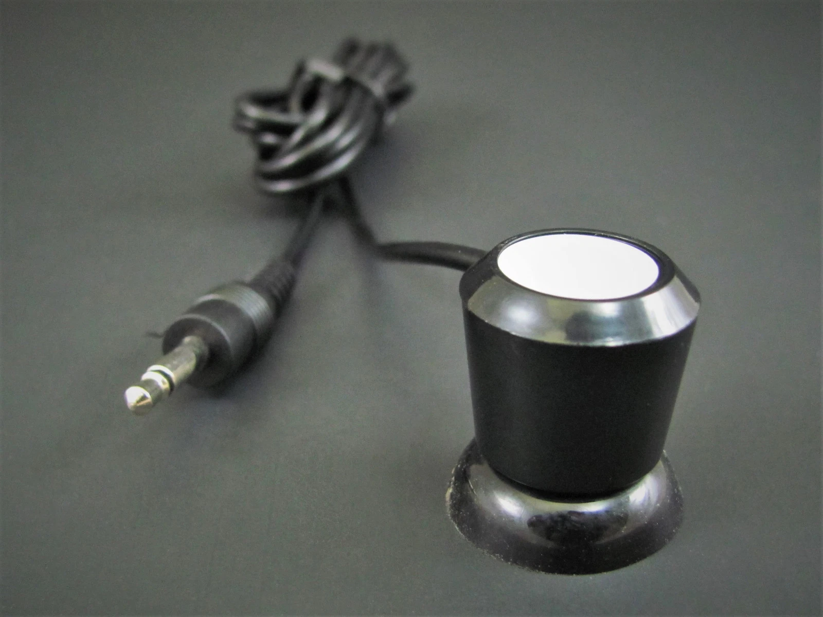 M81 telephone induction pickup coil, product view.
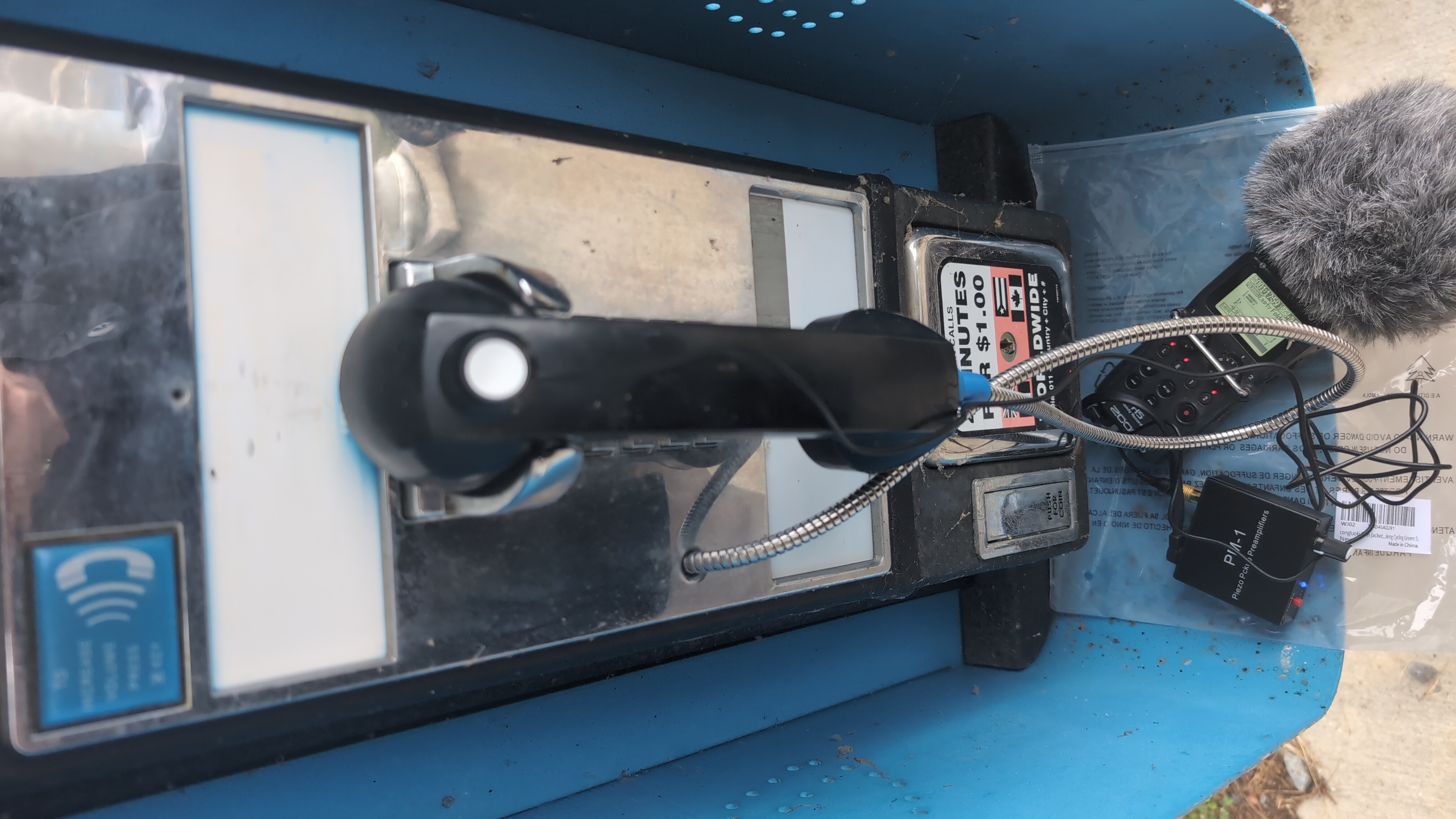 The same pickup in use on a payphone handset with the complete field recording chain.